
Defrauding a heat pump for fun and profit
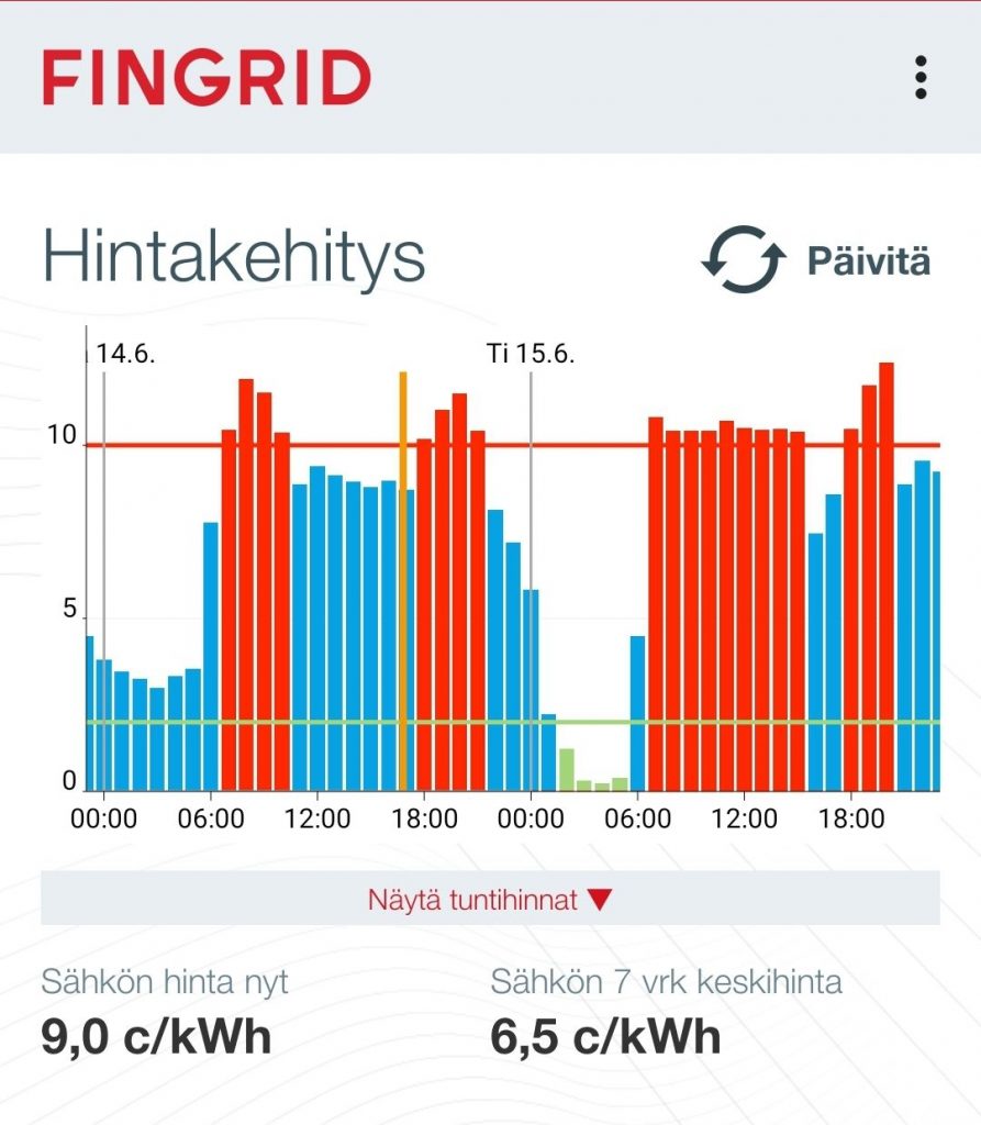
Bygone are the days when the kWh of electricity you consumed had the same cost regardless of the time. Now the effective price is not only the function of time and your contract with the energy provider, but there might also be some local generation to take into account. In Markus’ case a 10kWp photovoltaic plant is delivering a highly variable amount of free power and per the contract, grid power is priced by the Nord Pool Spot marketplace. Combined with the 500 litre warm water accumulator, picking the cheapest time to run the ground source heat pump warming the home has some considerable potential for cost savings.
The price of the electrical energy itself is not the only expense. There is also transfer price, which depends of the local grid operator and your contract. For regular customers it’s often a fixed price per unit of energy transferred, but there are time based plans available as well. And the taxes, too! So in practice you’ll often pay 5–10 euro cents per kWh on top of the spot price. And naturally, when selling your own production back to the grid, you are only paid of the electrical energy. The grid operators are like gambling houses. Always winning.
So, there is a clear incentive to avoid selling the electricity back to the grid, if we can just make our own loads flexible enough to match our own production.
Let’s pull the leg!
Into the control logic then. The original heat pump controller (circa 2007) is not terribly smart, but only takes into account the thermistor readings: if the warm water reservoir has cooled enough, it’s time to run the pump until it’s warm enough. The warmer the outdoor air gets, the less warm water should be mixed into the heating circulation. And so on, pretty basic stuff. How then can we integrate the smarter inputs into this? Via the thermistor lines of course!
A thermistor is a type of resistor whose resistance is strongly dependent on temperature, more so than in standard resistors.
Thermistor – Wikipedia
The controller applies some known reference voltage to a circuit of a fixed-value resistor and a thermistor and measures the voltage over the thermistor. From this, the resistance of the thermistor can be calculated and thus the temperature. When the temperature is high enough, the control logic does not start the heat pump. We exploit this logic by tricking the controller to conclude the thermistor to be warmer than it really is to control when the heat pump can run.
In this particular case the thermistor has negative thermal coefficient, in short NTC, so driving the voltage lower results in higher temperature readings. That’s exactly what we want to achieve.
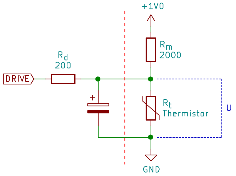
On the left: Defrauder circuit.
Joel got inspired by the possibilities and designed a device, the pumpunjuksautin, to make this control happen. First sketch used ATmega32u4 based Pro Micro as a daughterboard. But after a while Joel found out we need ICs with tiny footprints which are cumbersome to solder, so we just went for pick and place at JLCPCB factory. Unfortunately there was a some kind of global shortage of ATmega32u4 chips, so Joel had to once again redesign the board, this time having ATmega328p microcontroller instead.
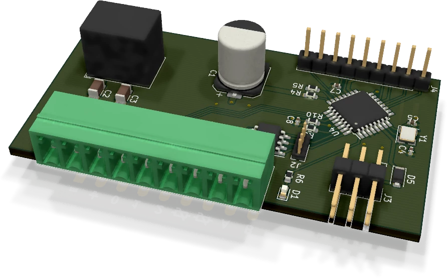
Partly because KiCad has so nice PCB view Joel exported the 3D model as a VRML and after a conversion in Blender to STL format managed to get it to OpenSCAD. In there it was quite straightforward to design a matching case for it because the 3D model has all the components and connectors already there.


The design has a rail for the PCB and a DIN rail clip in the back. When the PCB has been pushed in, the front cover keeps it in place.
Side note: Having 3D model of the PCB and the enclosure means you can 3D-print them both and test the fit before manufacturing anything. 🙂 And of course you should do it!
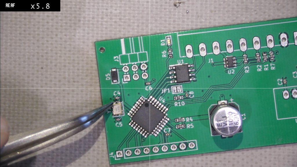
JLCPCB was quite fast to manufacture the batch. It took only about a week after placing the order to receive the package. However there was some mistakes in the design. Most fatal issue was an incorrect footprint for the crystal. Joel needed to add a tiny jumper wire to make it work.
Current status
With the current firmware and configuration the system disallows the heat pump from running during the manually picked typically most expensive hours (06–09, 16–00, accounting for typical cycle of spot market price and solar production). The next development steps are to enable the firmware to communicate in Modbus RTU instead of plain RS485 and to have more useful readouts from the connected thermistors. The control logic beyond the current wall time based implementation is a big missing piece, integrating the electricity price, the production/consumption balance and the temperature readings to automatically determine the most cost effective hours of heating without compromising the heat indoors.
So, hopefully this is just a first part of a longer story. The final target is there in the horizon: To match the local electricity consumption with local production. No electrons for sale!
All the firmware code, enclosure 3D model, schematics and PCB layout are at github.com/zouppen/pumpunjuksautin. Star us on GitHub and enjoy!
– -Zouppen and Maakuth
comments
Add comment